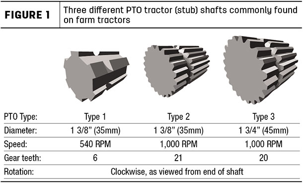
Today’s tractors are equipped with a PTO consisting of an external shaft at the rear of the tractor (Figure 1). In some applications, the tractor will be equipped with a three-point hitch on the front of the tractor that will be equipped with an external PTO shaft.
Be sure to always consult your operator’s manual to see what equipment and procedures you will need to follow when working on a machine’s PTO. Remember, each machine is different, and some of the information below may not apply.
Components of PTO drivelines
Figure 2 is a diagram of the components of two typical implement PTO drivelines. The upper drawing is a design that uses a pedestal connection between the tractor and implement.
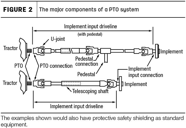
This style can be found on various types of pulled machinery like hay balers, mowers and rakes.
The lower drawing on the diagram is a driveline connection system that goes directly from the tractor PTO stub shaft to the implement’s input drive. Examples of this style of connection would be three-point hitch-mounted implements including mowers, tedders, rakes and posthole diggers.
The flexible U-joint makes the connection from the tractor to the implement. The U-joints are connected by means of telescoping profile tubes. The telescoping profile tubes will come in various shapes as well as designs depending on the application and manufacturer.
In addition to the standard universal single cardan U-joint, there is also a constant velocity (CV) joint design for driveline applications that requires a wider range of motion when making turns.
Driveline installation
There are a few important rules to follow when installing a PTO driveline from the tractor to the implement. You need to ensure the profile tubes will not “bottom out” against the U-joints, which can cause damage to both the tractor and the implement gearbox.
This is important to watch because the dimensions from the end of the tractor stub shaft to the drawbar or hitch arms will vary between tractor brands. Most manufacturers of PTO-driven equipment will supply a driveline length many times longer than is needed. It is important to respect the maximum and minimum overlap as listed in the machine operator’s manual.
When installing your driveline, first attach the machine and tractor, then separate the PTO driveline halves. Next, connect the driveline halves to the machine’s input drive and the tractor PTO stub shaft.
It is important to note some drivelines will be equipped with a radial pin or slip clutch, which is always mounted on the machine input side. With the two halves next to each other, place the machine in the transport position and with the tractor turned in a direction that will check for maximum overlap.
With the PTO shaft in the maximum overlap position (retracted), the profile tubes should not hit the yokes. As a general safety measure, a clearance of 1 to 2 inches must be maintained.
It is important to note if you need to shorten the profile tubes and guards, be sure to shorten both the tractor half and the implement half. Also check the PTO shaft in the maximum (extended) position to check for adequate profile tube overlap. Using the implement’s operator’s manual as a guide, you want to achieve the maximum overlap possible.
Finally, make sure the PTO driveline U-joints are in phase (or in line with each other) when reassembling the two halves. This is to ensure a smooth running driveline. Most profile tubes will have a design that ensures U-joint phasing.
Lubrication and routine checks
The importance of proper lubrication of the PTO shaft components, including the protective shielding, is critical to the reliability and performance of the driveline.
The proper grease type, along with the intervals and amount of grease, can be found in the machine operator’s manual. The standard grease for most drivelines should meet the National Lubricating Grease Institute (NLGI) No. 2 EP specification, unless otherwise noted by the manufacturer.
Operators should perform daily inspection checks of the driveline, including the protective shields. This should also include doing a regular test to make sure the shields are in place and can rotate freely.
If the driveline’s protective shielding is equipped with guard restraint chains, be sure they are properly attached to allow for movement of the driveline during turns. The lubrication of the bearings that hold the protective shields in place on the profile tubes is important too and should also be completed daily.
After lubrication and maintenance, check that the PTO shaft is securely attached to the tractor and machine before heading out to the field.
Safety first
Safety always comes first when working on or operating machinery. The speed of a tractor PTO, at 540 rpms for example, means the shaft is rotating nine times per second. When working on a driveline, your reaction time is not nearly as fast as the revolutions, so be sure to do the following to ensure your safety:
- Disengage the PTO and stop the engine before dismounting and working on the machine or driveline.
- Keep all guards in place on both the tractor and driveline.
- Walk around a machine or tractor rather than stepping over a rotating shaft.
- Instruct all operators about the hazards of the PTO driveline.
It all starts with proper attachment, maintenance and care of the driveline. By following these basic tips, you can be assured of the reliability of your PTO and your safety.
This tip list is a broad overview for understanding your PTO driveline. Please consult your machine operator’s manual or contact your local dealer, as each machine is different. ![]()
Ed Skeele is a technical support secialist with Kuhn North America